Whitepaper: Servo Valve Design for Faster Response in Motion Systems and also Low Contamination Susceptibility.
ABSTRACT
Servo valves are continuing to experience more demand as time goes on due to affordable sophisticated electronic controls that are now more available than ever in the market today. The problem with most of these torque motor driven, piloted type servo valves is the susceptibility of these valves to contamination. This can result in premature wear and failures due to the pilot stage becoming blocked with contaminant. Small orifices can get clogged and feedback devices can wear out. There also is a low limit to the step response and the frequencies that are achievable with this traditional design.
INTRODUCTION
The purpose of the linear servo valve design is to address these limitations by eliminating the parts of the design susceptible to these wear and contamination problems while also achieving faster flow response to electrical input signals. This linear spool drive design uses a coil that acts as a linear motor to drive the spool to the correct position when an electric feedback device is attached to the spool. This is done in such a way that the response time is improved and accuracy is improved compared to the pilot type. In addition, the contamination levels that are required are reduced to an ISO4406 21/19/16 level. This valve design can be produced in designs that range from D03 through D10. The valve designs are possible with off board electronics as well as on board electronics. Step responses of 2 ms to 100% flow are possible in the smaller sizes and frequency responses of up to 450 hz at -90-degree phase lag at 25% of full signal input. The compromise that is necessary in this design is that a separate amplifier is required to receive the feedback signal as well as produce a fairly large electrical power output to the valve in the 100 to 200-watt range.
MAIN SECTION
HIGH SPEED LINEAR SERVO VALVE
Development of the high-speed linear servo valve
Hydraulic controls are commonly used in mechanical drive systems for industrial equipment and machinery. In addition to the actuation of mechanical systems based on electric commands, they typically employ electro-hydraulic servo valves or proportional electro-hydraulic directional and flow control valves with sensors for position, speed, acceleration, pressure, and load control. A “high speed linear servo valve” replaces conventional nozzle flapper-type electro-hydraulic servo valves. By incorporating a voice coil linear motor as a control actuator, the valve can be put into commercial use.
High speed linear servo valves have been designed to provide a frequency response of 400 Hz or more, which is approximately twice that of most nozzle flapper-type servo valves (100 to 200 Hz). For commercialisation, the valves have also been designed to offer long service life, high reliability (tolerance to hydraulic fluid contamination), and energy savings. These linear servo valves are being applied in a wide range of areas, because of their excellent performance and reliability.
Structure and operation
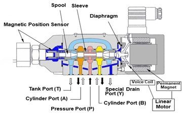
Linear servo valves control the flow and direction of hydraulic fluid by moving the spool for flow passage control. With the spool coupled directly to a compact, high thrust voice coil linear motor,
the valve operates under electrical feedback control using a dedicated high-speed amplifier (Figure 1). The valves structure is shown in Figure 2.
Figure 1
Figure 2
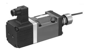
The valve comprises a body (Figure 3), a linear motor, and a position sensor, with a high-power neodymium-iron-boron (Nd-Fe-B) permanent magnet placed in a fixed position and a movable coil out of contact with the permanent magnet and the yoke. The position sensor is a non-contact high response magnetic sensor. The valve has a simple structure and lightweight movable parts; it is user-friendly with high response and tolerance to hydraulic fluid contamination (allowing for a contamination level of NAS class 10).
Specifications and performance
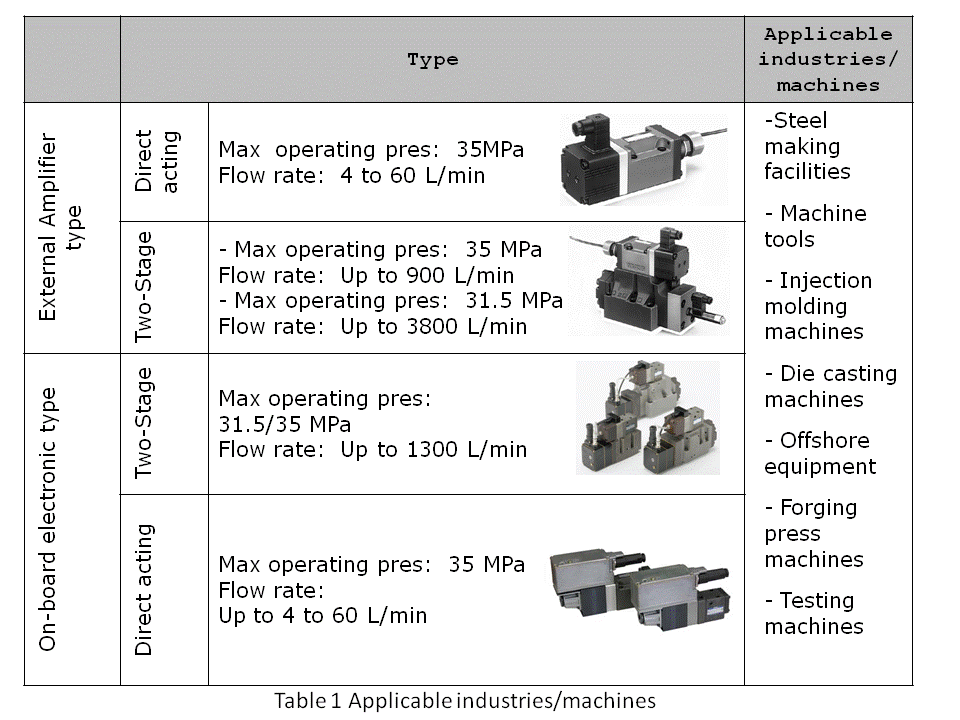
Linear servo valves have been adopted in applications with a maximum operating pressure of 35 MPa and a flow rate of 4 to 3,800 L/min. They support a wide range of flow rates, performance requirements, and functions. Basically, the valve is a single stage servo valve configured as described above and operates at a flow rate of 4 to 60 L/min, a frequency response of 450 Hz/-90°, and a step response (0 <=>100 %) of 2 msec. At higher flow rates, the two-stage type of the valve is employed and operates at a frequency response of about 100 Hz/-90° and a step response (0 <=> 100 %) of 8 to 12 msec (representative performance see Figures 4 & 5).
CONCLUSION
Because of their high response, linear servo valves are used in injection moulding machines that deliver a resin filling speed of 1,000 to 1,500 mm/sec in 8 to 12 msec and die casting machines that deliver an aluminium filling speed of 4 m/sec or a magnesium
filling speed of 8 m/sec. Since the valve has excellent accuracy and response capability, they are also used in various testing machines. The tolerance to hydraulic fluid contamination is useful in steel making facilities and other mill type environments (see Table 1).
CONTACT
AUTHOR: LEN KASTER
https://alaindustrieslimited.com/yuken
Yuken Europe Ltd.
51 Spindus Road, Speke, Liverpool, L24 1YA
www.yukeneurope.com
+44 (0)151 268 1890
office@yukeneurope.com


